Electronic Charity box
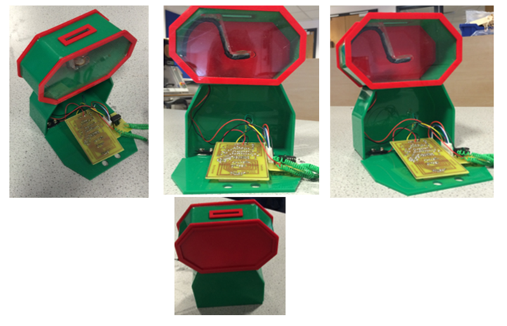
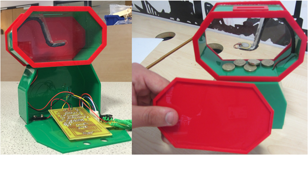
Here is the final product made. As you can see the circuit board is stored underneath and money can be retrieved by opening the front casing. Additionally, coins can be inserted from the top. Below you can see the process which lead to this.
Firstly, I began by carrying out market research, generating design ideas and evaluating the sustainability of the product. After this, I started to research possible components that could be used to achieve this such as the 7 segment display. Having gained a general idea of what I will do, I began to look into schematic designs and seeing how 7 segment displays work using switches.
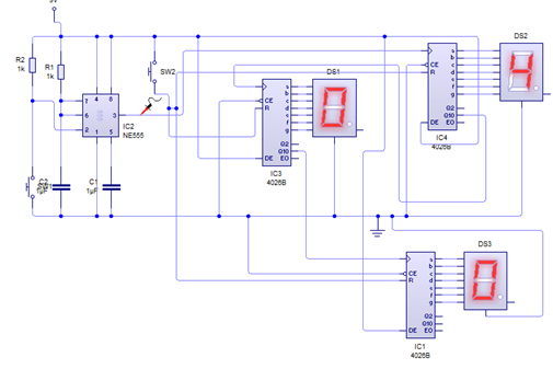
After using Circuit Wizard and EAGLE to look into different schematics I chose one which met the user criterea I had set earlier after my research.
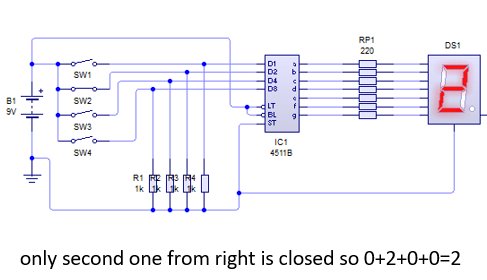
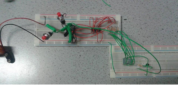
Before designing and making the PCB, I built a section of it with one segment display to see if it works in practice.
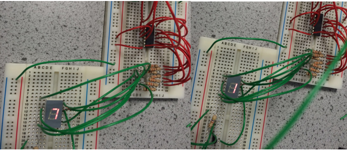
Below you can see a picture of it set at different numbers using the push to make switch.
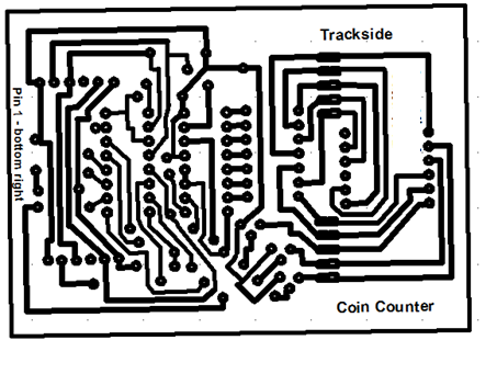
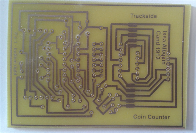
Having tested it in practice, I took all the necessary measurments from the datasheets of the components I had ordered and made a PCB design using 2D Design.
To make the circuit board, I printed this PCB on acetate paper. I cut out the correct size circuit board for it and then placed the acetate paper on this in the ultraviolet light box for an appropriate time period.
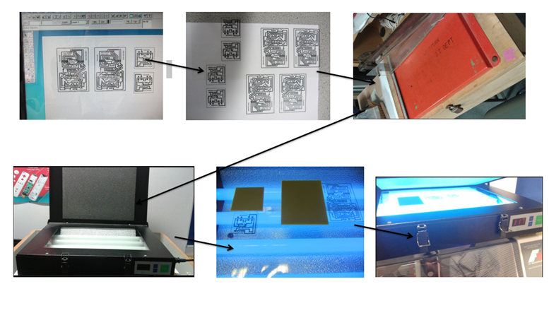
This was then shaken in a 15 to 1 mixture of water and hydrogen peroxide
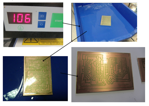
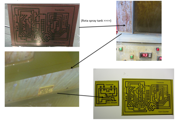
Finally, I put it into the spray etcher
After rubbing it with wire wool, it was ready.
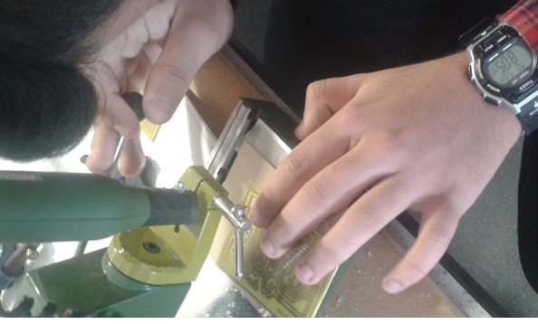
I then used a drilling machine to be able to use the pins
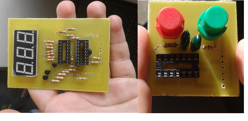
After soldering it, I had both the input circuit and the logic circuit that will be used.
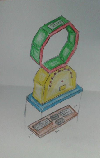
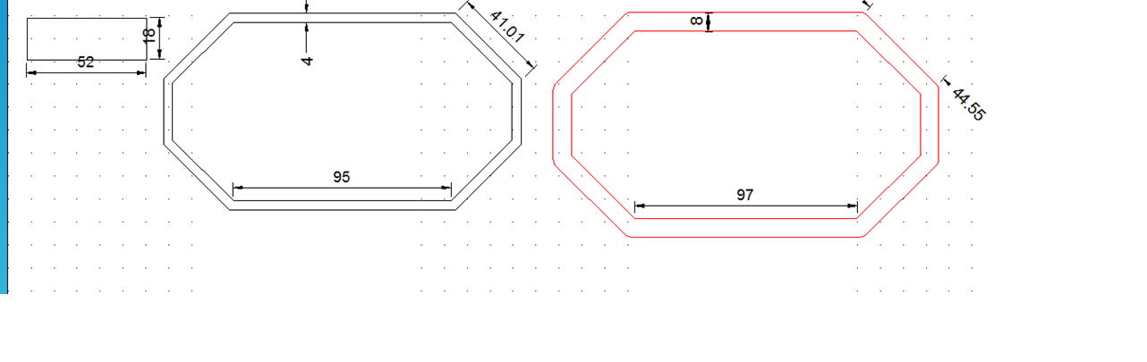
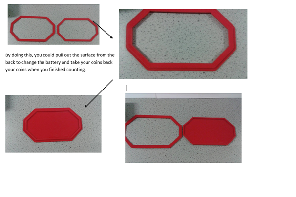
I sketched some casing ideas, this was the most suitable one.
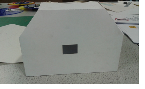
I did a test of what it would look like with cardboard
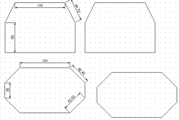
I used a laser machines to cut out the plastic and a line bender to get the intended shapes
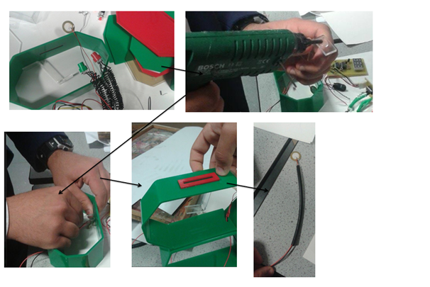
After putting everthing togather, I used velcro to secure the circuit and I finally, I had my final product